5 common causes of false alarms in optical flame detectors
A false alarm from an optical flame detector is easy to dismiss as an inconvenience. It rarely stays that way. Unnecessary shutdowns cost money. Repeated false alarms erode operator confidence, and once a team stops trusting their fire and gas detection, they start ignoring alerts. That's where it gets dangerous.
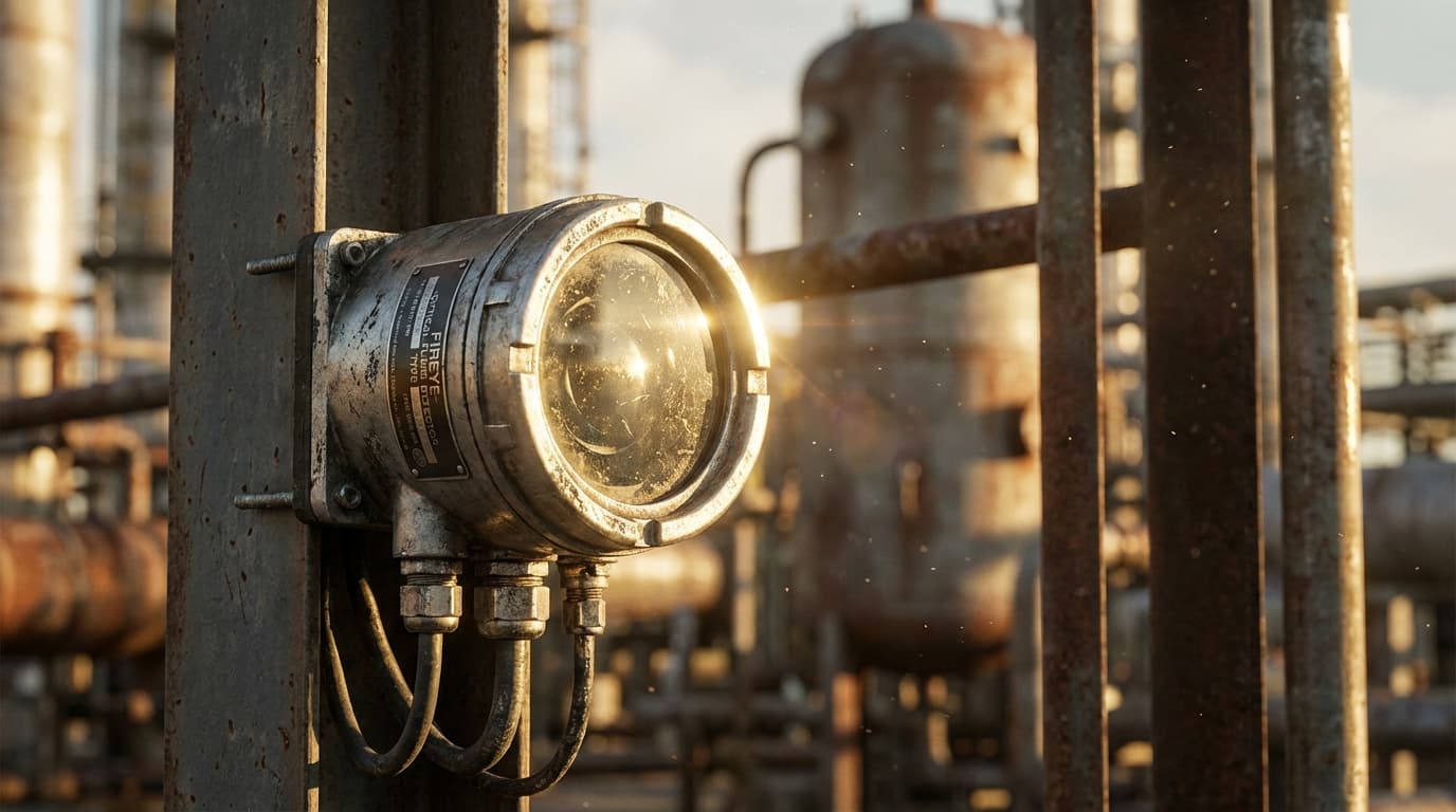
Optical flame detectors (UV, IR, UV/IR, IR3, and multi-spectrum types) don't simply "see fire." They analyse specific radiation wavelengths and, in more advanced designs, the flicker pattern characteristic of combustion. False alarms happen when something else in the plant environment produces a signal close enough to fool the detector. Most of the time, the cause is predictable and preventable.
Here are the five most common reasons.
1. Hot work: welding, cutting, grinding
This is the most frequent culprit at operating plants, and it catches facilities off guard more than it should.
Arc welding produces intense broadband UV radiation that falls within the detection band of UV sensors. IR detectors respond to the radiant heat from sparks, molten metal droplets, and the thermal output of gas cutting. Even a brief burst of hot work inside a detector's field of view can look convincingly like a real flame event.
The problem compounds with UV/IR combination detectors. If a strong IR source from a hot process surface is already partially satisfying the IR channel, the detector effectively behaves like a single-band UV detector and becomes more susceptible to welding arcs and electrical discharges triggering a full alarm.
What helps: A strict hot work permit system with formal detector inhibition procedures. Not ad hoc bypassing, but controlled inhibition under a documented management of change process, with the inhibit logged, time-limited, and signed off. Detectors in areas with routine maintenance activity should also be reviewed for repositioning or physical shielding during the design phase.
2. Sunlight and reflective surfaces
Sunlight alone doesn't typically trip a well-specified modern detector. The problem is what sunlight does when it bounces off polished stainless steel, glass surfaces, vehicle windscreens, standing water, or rotating equipment.
A changing reflection can mimic the 1–20 Hz flicker frequency that flame detectors use to distinguish a real fire from steady background radiation. Sunrise and sunset are particularly bad because the angle of light changes quickly, and reflections that didn't exist an hour ago suddenly appear.
For outdoor Southern African installations, solar loading is a real factor. The intensity of direct and reflected sunlight here is not the same as a covered process area in a temperate climate. Detectors without proper solar-blind filtering at the 4.3 µm CO₂ resonance band aren't suitable for outdoor use. Some cheaper IR detectors marketed for outdoor applications fall short in practice.
What helps: Walk the site at different times of day as part of your coverage mapping study. Avoid aiming detectors toward known reflective surfaces. Optical hoods and sunshades are cheap compared to the cost of a nuisance shutdown. For outdoor hydrocarbon applications, IR3 or multi-spectrum IR (MSIR) detectors offer much better immunity to solar interference.
3. Hot process equipment and blackbody radiation
Furnaces, heat exchangers, flare stacks, turbine exhausts, hot piping, and heaters all radiate infrared energy continuously. By itself, that steady-state radiation is usually manageable. Most modern IR detectors are designed to filter it out.
The problem is modulation. When that radiation gets interrupted, whether by a vehicle crossing the line of sight, fan blades rotating, someone walking past, or a detector swaying in the wind, the previously steady IR source starts flickering. That flickering can look exactly like a flame to a single or dual-band IR detector.
Turbine and engine exhaust gases are a specific problem for IR3 detectors because hot CO₂ from combustion exhaust is exactly what IR3 technology is designed to detect. Applications like tanker loading racks or aircraft hangars need either specialised detector configurations or a different technology altogether.
What helps: Choose detector technology based on the radiation environment, not just the fire hazard. Run a radiation survey during the F&G mapping phase to identify process hot spots and keep them out of detector fields of view where possible. IR3 and MSIR detectors with multi-wavelength ratio discrimination handle high background thermal radiation better than single-band IR.
4. Poor installation and incorrect configuration
This one gets misdiagnosed as a detector fault all the time. The hardware is fine. The problem is where it's pointing and how it's set.
Common issues: detectors aimed too broadly across active work areas or plant roads, sensitivity cranked higher than the hazard requires, time delays set too short, and fields of view that nobody verified after commissioning. Sometimes the detector is simply the wrong type for the application, like a UV detector in an outdoor area where solar loading will cause chronic nuisance trips.
Overlapping fields of view without appropriate voting logic is another design issue that shows up in alarm histories. Two detectors covering the same zone without a 2-of-2 or 2-of-3 voting configuration means any single false trigger goes straight through to alarm.
This is a design and commissioning failure, not an operational one. Review early alarm history after startup. The pattern usually makes the cause obvious.
What helps: Base detector placement on a proper fire and gas mapping study tied to the site-specific hazard analysis. Verify settings against the Safety Requirements Specification. Post-commissioning walk-downs with alarm history review should be standard in the F&G system handover.
5. Contaminated optics and harsh environmental conditions
Dirty detector windows affect performance in ways that aren't always obvious. Heavy contamination usually reduces sensitivity: the detector goes partially blind without triggering any alarm, which is arguably worse than a false alarm. But in marginal or transitional contamination states, unstable signals and nuisance trips can occur.
Common contaminants in Southern African process environments include dust, oil mist from process equipment, salt spray at coastal facilities, condensation and ice in cold installations, and insects or spider webs on the lens. Water on the optical window is particularly problematic because it absorbs in the mid-band IR range where most IR, IR3, and UV/IR detectors operate, distorting the spectral signal in ways the detector can misinterpret.
One detail worth knowing: optical self-test fault indicators in most detectors only activate after sensitivity has dropped by around 50%. At that point, a fire would need to be roughly four times its normal detectable size to register. The fault indicator is a lagging signal, not an early warning.
What helps: Scheduled cleaning on a defined interval, adjusted for actual site conditions. Quarterly or monthly at dirty or coastal sites, not annually by default. Weather shields and air-purge systems where the environment warrants it. Heated optics in cold or wet locations. Self-diagnostic features are a backstop, not a substitute for regular inspection.
The pattern behind the problem
False alarms in optical flame detectors are rarely random. They follow predictable patterns tied to site conditions, detector selection, installation decisions, and maintenance discipline. Under IEC 61511, a high nuisance trip rate degrades SIS availability and creates pressure to bypass detectors, which undermines the entire safety layer.
The fixes are usually straightforward once you identify the root cause. The harder part is building the maintenance records and alarm review discipline to catch problems early, before they become habitual.
This article is a general overview for plant operators and maintenance personnel. For site-specific flame detector selection, placement optimisation, or false alarm diagnostic support, consult a qualified fire and gas engineer with relevant process industry experience.
Reviewed by a qualified engineer
Thabo Matona
Founder and Principal Engineer, Touch Teq Engineering
This article is published by Touch Teq Engineering and reviewed for technical accuracy by an engineer overseeing industrial fire and gas detection, control and instrumentation, hazardous area classification, and electrical engineering work in Southern Africa.
Last reviewed: March 2026
Relevant domains: Fire and gas detection, Optical flame detectors, Maintenance strategy, Alarm reduction.